Role of subsystem in vehicle
The Energy Storage System (ESS) block represents the battery pack that stores energy on board the modeled vehicle. This block accepts a power request, usually from the power bus, and returns available/actual power output from the battery, the battery voltage and current, and the battery State of Charge (SOC). By convention, positive power is discharge.
Description of modeling approach
The ESS block models the battery pack as a charge reservoir and an equivalent circuit whose parameters are a function of the remaining charge in the reservoir. The equivalent circuit accounts for the circuit parameters of the battery pack as if it were a perfect open circuit voltage source in series with an internal resistance. The amount of charge that the ESS can hold is taken as constant, and the battery is subject to a minimum voltage limit. The amount of charge that is required to replenish the battery after discharge is affected by coulombic efficiency. The charging of the battery is limited by a maximum battery voltage. While the battery is treated as a perfect electrical voltage source with a known resistance, the components to which the battery would be connected, such as a motor or a generator, are treated as power sources or sinks. Power delivered by the battery is limited to the maximum that the equivalent circuit can deliver or the maximum that the motor controller can accept, given its minimum voltage requirement.
Other relevant glossary terms include: Capacity, Rated Capacity, C/N rate, N hour rate, and [Peukert’s equation](glossary.html#Peukert’s%20Equation).
A simple single-node thermal model of the battery is implemented with parallel flow air cooling. More detail can be found in the battery thermal model explanation.
Variables used in subsystem
See Appendix A.2: Input Variables
See Appendix A.3: Output Variables
Implementation
Energy Storage System (Top level)
As described above, the energy storage model computes the battery SOC in response to the requirements of the power bus and outputs the available power. Power loss is computed as I2R losses plus losses due to Coulombic (in)efficiency. A step-by-step explanation follows.

Each of these sub-blocks is explained below.
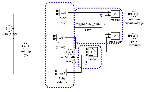
1. Pack Open Circuit Voltage and Internal Resistance: This block calculates Voc and Rint given the current SOC and required battery power.

2. Limit Power:This block prevents the power that is used to compute the battery current from exceeding limits imposed by three limits: SOC, equivalent circuit parameters, and the motor controller’s minimum allowable voltage.

 where Vbus is either Voc/2, the minimum motor controller voltage, or the minimum battery voltage, whichever is larger.
3. Compute Current:This block solves the quadratic equation for current that is derived by starting with the definition of electrical power and Kirchoff’s voltage law (KVL) for the equivalent circuit shown below.
Block Diagram
- Current is determined. Power is defined as: P=V x I, or V=P/I. Combining the power equation with KVL yields: P/I=Voc-(R x I). Multiplying both sides of the equation by I yields P = (Voc x I) - RI2 . This is the equation that is solved in the block diagram: RI2 - (Voc x I) + P = 0. There are actually two solutions for this equation, but the larger solution is not considered because it would require larger current, and thus a lower terminal voltage, to produce the same power. All solutions that require a terminal (or bus) voltage less than half the battery’s open circuit voltage are thus not considered. During charge, the maximum voltage must not be exceeded. This maximum charge current (or minimum raw value of current since charging is a negative current) is found from I=(Voc-Vmax)/R.
- Bus voltage is determined. Kirchoff’s voltage law, applied along the equivalent circuit loop, requires that: V=Voc-(RxI).
4. SOC algorithm:The state of charge (SOC) algorithm in ADVISOR is responsible for determining the residual capacity, in units of Amp-hours (charge), that remains available for discharge from the battery. It approximates this value in a series of steps. Note that the coulombic efficiency and maximum capacity are functions of temperature.

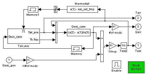
5. Thermal model: A simple, single-node lumped-parameter thermal model was added to the ESS (energy storage system) sub-block of the ADVISOR. This thermal model predicts the average internal battery temperature and surface (case) temperature as a function of time while the vehicle is driven and during soak periods. Currently there is only one cooling option: parallel-flow air cooling (each module has the same air flow and inlet air temperature, which are specified by the user). See the battery thermal model explanation for more details.

Last Revised: 5/29/01: vhj