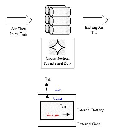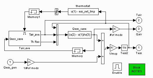
Figure 1: Schematic of ESS thermal model
Summary
A simple, single-node lumped-parameter thermal model within the ESS block predicts the average internal battery temperature and exiting air temperature as a function of time while the vehicle is driven and during soak periods. Currently there is only one cooling option: parallel-flow air cooling (each module has the same air flow and inlet air temperature, which are specified by the user).

Figure 1: Schematic of ESS thermal model
Qess_case
This is a combination of the conduction and convection from the internal battery to the air. Airflow over the battery begins once the temperature has exceeded a setpoint, ess_set_tmp. The effective thermal resistance is calculated as follows:

and Qess_case=(Tess-Tair)/Reff.
Tair
The effective air temperature to which the battery convects is slightly warmer than ambient temperature. 50% of the energy going into the air is assumed to go towards warming the air up. 
Tess
The heat generated by the battery is calculated from coulombic and internal resistance losses. The temperature of the battery is calculated to be: 
Battery Thermal Model
This model provides preliminary indication of the battery temperature versus time for a variety of battery, vehicle, and drive cycle combinations. In some cases, active battery thermal management may not be required. In many others, battery temperature objectives may be able to be met with simple air cooling. In some extreme cases, air cooling may not be sufficient and liquid cooling may need to be considered.
The top level of the new ADVISOR battery thermal model is shown in Figure 2. It consists of a single lumped thermal mass representing one module, excluding its case. Since many modules have a plastic case, and this case can provide a significant thermal resistance to heat flow, the module case was treated separately. Although its thermal resistance can be significant, its thermal mass relative to that of the module is very small. Hence, the case thermal mass is not explicitly modeled (whatever heat flows into the case from the module is assumed to flow out via convection and radiation).

A variety of active cooling conditions are possible with battery packs, including air versus liquid and parallel flow versus series. Initially, only one common approach has been modeled: that of parallel air flow. This approach is used in the Toyota Prius (Japanese) and has also been used at NREL for domestic automaker HEV pack development. In this approach, the cooling air is distributed (usually) under the pack and flows up along each module, then is collected in a space above the pack and exhausted. This has the advantage that every module sees the same inlet air temperature, which leads to a more uniform pack temperature. From a modeling standpoint, it means that the pack thermal behavior can be reasonably represented by modeling a single module.
After specifying the module mass, average heat capacity, case thickness, and case thermal conductivity, the two additional items needed are the module heat generation rate (versus time) and the heat loss from the surface of the module case. As mentioned previously, the battery heat generation is currently modeled via I2R losses plus losses due to Coulombic (in)efficiency. The Coulombic efficiency is a measure of the heat generated or absorbed due to the chemical reactions of the battery cell. For the current empirical-based model, this efficiency is assumed to be a constant. For theoretical battery models, the chemical reactions can be solved for explicitly. This will be the case with the new model by Dr. Harb of BYU, when it is incorporated into ADVISOR in the next few months.
Concerning the heat loss from the module case surface, radiative and convective heat losses were both estimated. The radiative heat loss is estimated from the surface area exposed to ambient and the case emissivity. The convective loss is a function of the case surface area exposed to the cooling air and the average air heat transfer coefficient over the case. This heat transfer coefficient is estimated from correlations from “Fundamentals of Heat and Mass Transfer”, by Incropera & DeWitt and includes a minimum value based on natural convection. The user specifies the mass flow rate of cooling air per module. In parallel flow, the total pack air flow is the product of this per-module air flow and the number of modules in the pack. Currently the cooling air inlet temperature is set to ambient. A cabin thermal model will soon be added to ADVISOR, after which the user will have the option to have the battery cooling air match the cabin air temperature.
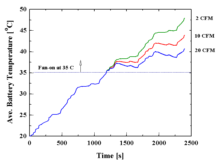
A thermostat feature is also included. By specifying a set temperature, the airflow will start only after the battery temperature rises above this value. An example of the thermostat and airflow effects is shown in Figure 3. In this case (series HEV running 4 US06 cycles), the set temperature was 35 C, after which the fan came on to deliver either 2, 10, or 20 CFM per module (50, 250, or 500 CFM for the pack).

The effect of drive cycle on battery temperature can be seen in Figure 4. The same vehicle (series HEV with lead/acid batteries, 10 CFM cooling air, 35 C set temperature) is run on 4 US06 cycles and 4 SC03 cycles. Because the US06 cycle is much more energy-intensive, there is more waste heat generated in the batteries, resulting in a more rapid heat-up.

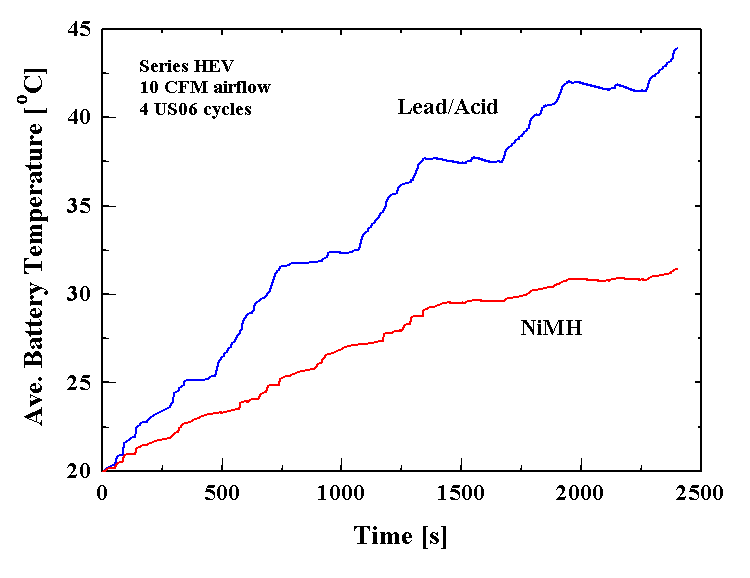
Finally, Figure 5 shows the effect of battery type. A series HEV with 10 CFM cooling air per module is run on 4 US06 cycles using lead/acid and NiMH batteries. The NiMH pack remains cooler because it has a lower internal resistance and generates less heat.

Future Activities
The current ADVISOR battery model now includes thermal effects. In the future, the battery thermal model will be enhanced to include other types of active cooling such as liquid cooling and series flow.
Last revised: 1/18/01, vhj