Regenerative Braking
Regenerative braking is the process by which some of the kinetic energy stored in the vehicle’s translating mass is stored in the vehicle during decelerations. In most electric and hybrid electric vehicles on the road today, this is accomplished by operating the traction motor as a generator, providing braking torque to the wheels and recharging the traction batteries. The energy provided by regenerative braking can then be used for propulsion or to power vehicle accessories.
Overview
Of the total braking torque required, X% will be performed by the driveline (motor, engine, trans, etc.) and 100-X% is performed by
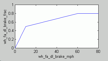
the friction brakes. X is defined as a function of vehicle speed by the inputs wh_fa_dl_brake_frac and wh_fa_dl_brake_mph. By default, driveline braking is used less at low vehicle speeds than at high speeds. Then, of the X% performed by the driveline, the available regenerative braking energy minus any efficiency losses of components through which the energy must flow (ie., gearbox, motor/controller, energy storage system) is captured by the energy storage system.

Example
This example shows how ADVISOR’s brake controller block cooperates with the drivetrain component models to model a regenerative braking event.
In this example, an electric vehicle decelerates from 17.3 m/s (38.8 mph) to 0 in 10 s. The figure below shows the vehicle speed and tractive force required.

To achieve the required deceleration, the required tractive force is negative. (Note that if the required deceleration were at the same rate as an unpowered coastdown, the required tractive force would be zero because aerodynamic drag and rolling resistance would be enough to cause the required deceleration.) This indicates an opportunity for regenerative braking.
The data in the figure above are passed from the vehicle <veh> block to the wheel and axle <wh> block which in turn exchanges data with the braking control block. This block uses required speed and required force to determine how much braking will be done by the front-axle friction brakes, the rear-axle friction brakes, and the driveline. The braking done by the driveline is the regenerative braking. However, it is important to recognize that not all of the driveline braking energy can be stored–on its way from the wheel and axle, through the drivetrain and electric motor, and into the energy storage system (usually electrochemical batteries), this braking energy incurs losses.

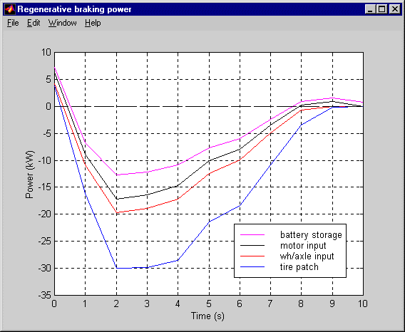
The figure above shows that the regenerative braking power required into the wheel/axle assembly is whittled away by component losses as it moves up the driveline. At 2 s, the braking power required at the tire patch (computed as veh_spd_r*veh_force_r) is 30 kW, while the braking power required where the wheel/axle interfaces with the final drive (computed as wh_trq_r*wh_spd_r) is 20 kW. 10 kW is consumed by axle losses and by the friction brakes. (The variables wh_fa_fric_brake_frac, wh_fa_fric_brake_mph, wh_fa_dl_brake_frac, and wh_fa_dl_brake_mph control how much friction and driveline/regen braking is commanded as a function of speed. Follow this link for more info on these variables.) About 3 kW is lost in the transmission and motor, accounting for the difference between the red and black curves at 2 s. Another 5 kW or so is lost in the energy storage system, leaving about 12.5 kW (x 1 s = 12.5 kJ) making it into storage.
Measuring the effect of regenerative braking
Let’s assume we wish to see how much a particular regenerative braking scheme improves EV range.
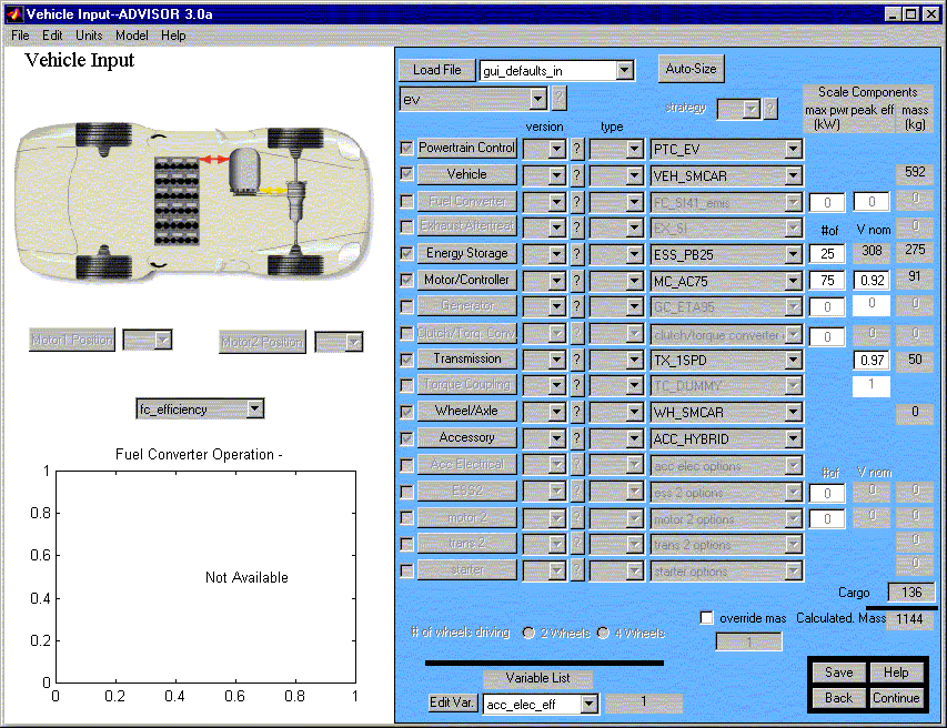
First, we define our vehicle, with the regenerative braking scheme active. (The relevant data is the WH_*.m input data file.)

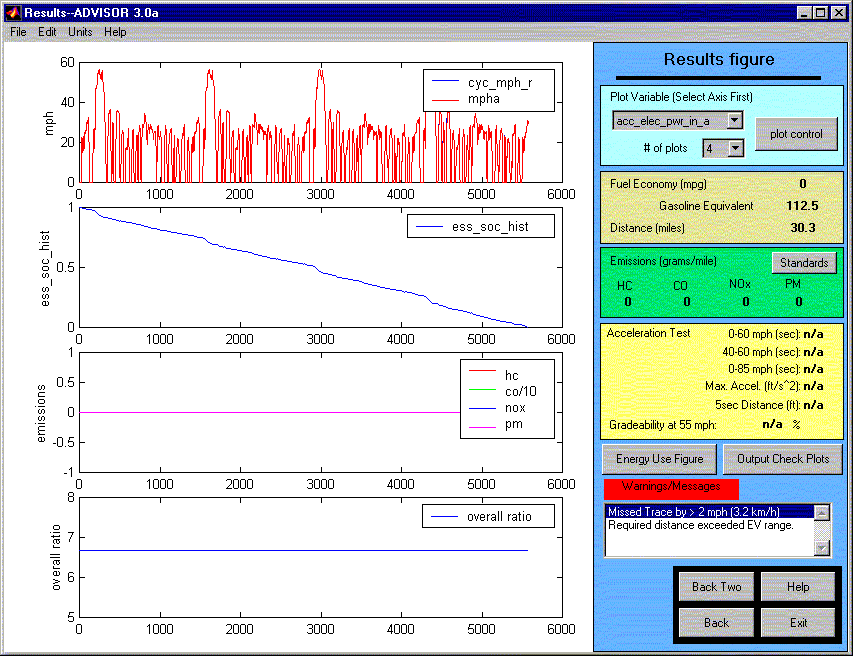
Then, we run the vehicle on CYC_UDDS, using default Simulation Setup parameters except for ‘# of cycles,’ which we set at 5. This results in a distance of 30.3 miles, as seen below.

We now hit the ‘Back Two’ button to again see the Vehicle Definition screen. At the MATLAB command window, we enter ‘wh_fa_dl_brake_frac,’ and MATLAB responds:
wh_fa_dl_brake_frac =
0 0 0.5000 0.8000 0.8000
To remove all regenerative braking, we enter
wh_fa_dl_brake_frac=[0 0 0 0 0];
We rerun the analysis using 5 x CYC_UDDS, and find the new range to be 26.8 miles.
* * * * *
Last Revised: 7/20/00:AB