Autosize Help
Overview
The purpose of the autosize function is to help the user generate a vehicle that will meet certain performance criteria. It accomplishes this by adjusting component sizes and reevaluating the performance criteria until all of the specifications have been met. Currently, two forms of this function are active in ADVISOR. The first is Matlab-based and uses a bisection method and some built-in logic to determine the acceptable component sizes. The second uses VisualDOC optimization software to determine the necessary component sizes. Either autosize routine only provides a single solution to the optimization problem. Therefore, the results should only be used as guide and not assumed to be the optimum for all objectives.
Autosize Configuration Window
The Autosize Configuration Window, shown in Figure 1, is accessed by clicking on the Autosize button from the Vehicle Input Screen. This interface allows you to adjust a variety of parameters that define how the autosize problem will be solved.

Figure 1: Autosize Configuration Window
Autosize Method Selection
To use VisualDOC as the solution engine for the autosize routine the user must select the “Autosize using VisualDOC” radiobutton. The default is to use Matlab as the solution engine. If VisualDOC is selected as the solution engine, ADVISOR will search for VisualDOC and determine whether the current version is a demonstration version or a licensed version. A demonstration version is provided with ADVISOR. This version is limited to 5 design variables and 20 constraints.
Constraints
This section defines the performance constraints that can be applied in sizing the vehicle. These include performance on a constant grade, maximum effort acceleration criteria, and maximum vehicle speed. By clicking on the Grade Options or Accel Options buttons the use will be able to view the current settings and also modify the settings as desired. Please see the help sections on the grade test or the accel test for more information on the available options.
Design Variables
Design variables are the components that will be adjusted by the autosize routine. Depending on the vehicle type and solution engine used, the user will be able to select the fuel converter, the energy storage system, the motor controller, the low SOC, and/or the high SOC.
When using Matlab, the physical components will be minimized and the control strategy-related values will be optimized based on the energy storage system characteristics based on the following relationships,
Series: cs_lo_soc = charge_soc
Parallel: cs_lo_soc = mean(charge_soc,discharge_soc)
where,
charge_soc = SOC associated with the minimum charge resistance
discharge_soc = SOC associated with the minimum discharge resistance.
The variable cs_lo_soc will also never be set lower than 0.3 by the autosize routine. If selected, the variable cs_hi_soc will be minimized such that the acceleration constraints are satisfied.
When using VisualDOC, the initial value defaults to the current size in the workspace and the candidate values define specific points that will always be evaluated by VisualDOC. The candidate values should be set to values the span the feasible solution space to ensure that VisualDOC finds the global optimum and not a local optimum.
Objectives
The possible objectives include any combination of the following; minimize component sizes, minimize vehicle mass, maximize combined city/highway fuel economy. When using Matlab as the solution engine, the only objective available is to minimize the component sizes.
If the objective is to minimize the component sizes, the routine will adjust the size (power output) of the components selected as design variables until they have been minimized while satisfying the constraints. If the objective is to minimize vehicle mass the component size (power output and thus mass) of the specified design variables will be adjusted until the mass of the vehicle has been minimized while satisfying the constraints. Finally, if the objective is to maximize the combined fuel economy, the routine will again adjust the size of the components specified as design variables until the combined city/highway fuel economy (see TEST_CITY_HWY documentation) has been maximized while satisfying all constraints. In order to determine the combined city/highway fuel economy, ADVISOR must simulate the vehicle over an FTP cycle and a federal highway cycle while using the zero delta SOC correction method. Thus, this objective will require a significant amount of simulation time. If multiple objectives have been selected they will be weighted equally by VisualDOC.
VisualDOC Optimization Parameters
By default, VisualDOC will use response surface approximations to solve the autosizing problem in order to shorten the solution time. The user can also specify the minimum and the maximum number of design cycles VisualDOC should perform. Several solution methods are also available and include Feasible Directions, SLP (Sequential Linear Programming) and SQP (Sequential Quadratic Programming). For more information on the solution methods used by VisualDOC please refer questions to Vanderplaats R&D (www.vrand.com).
Autosize using Matlab
The Matlab-based autosize routine uses a bisection method to determine the required component sizes based on the performance criteria specified. The method and order in which the components are sized depends on the vehicle in question.
Series Hybrid Vehicle
For a series hybrid vehicle (includes fuel cell vehicles since they are modeled as series hybrid vehicles), the grade constraint drives the required fuel converter size (and possibly the motor size) while the acceleration constraint drives the energy storage system size (and possibly the motor size). If the motor controller has been specified as a design variable it will be minimized if possible based on the acceleration constraints. Otherwise, it will be sized such that it will never limit the performance of the fuel converter or the energy storage system. Note that the variable, mc_overtrq_factor, will be set to 1 if the motor controller is a design variable. This assumes that the user does not want to exceed the maximum torque values of the motor for any extended period of time. The routine will exit once the constraints have been satisfied within the specified tolerance value.
Parallel Hybrid Vehicle
The autosize routine for a parallel vehicle is slightly more complicated. The parallel configuration provides an added level of flexibility in the power distribution. Thus, another vehicle parameter is introduced and is referred to as the ‘degree of hybridization’. It defines the relationship between the fuel converter size and the energy storage system size. If the level of hybridization is set to 1.0 the vehicle will have a very small fuel converter. If the level of hybridization is set to 0.0 the vehicle will have the smallest allowable energy storage system. Anything between 0.0 and 1.0 will provide some form of a moderate hybrid.
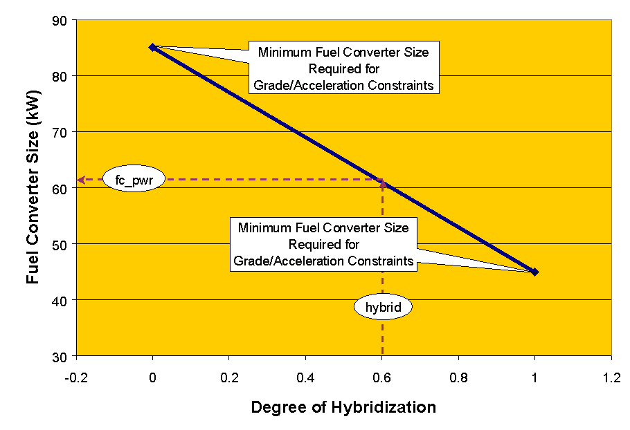
The autosize routine proceeds by first minimizing the entire energy storage system (including the motor/controller) and then determining the minimum fuel converter size to first meet the grade constraints and then the acceleration constraints. Then the fuel converter size is fixed based on the degree of hybridization term according to the following relationship (see Figure 2),
fc_pwr = min_fc_pwr + hybrid * (max_fc_pwr - min_fc_pwr)
where,
fc_pwr = new fuel converter size
min_fc_pwr = minimum of the fuel converter size required to meet the grade constraints and the fuel converter size required to meet the acceleration constraints
max_fc_pwr = maximum of the fuel converter size required to meet the grade constraints and the fuel converter size required to meet the acceleration constraints
hybrid = degree of hybridization (0.0 - 1.0).

Figure 2: Parallel Hybrid - Degree of Hybridization
Once the fuel converter size has been fixed the routine sizes the energy storage system to meet the acceleration requirements. If the motor controller has been specified as a design variable it will be minimized if possible based on the acceleration constraints. Otherwise, it will be sized such that it will never limit the performance of the energy storage system.
Conventional
By default, for the conventional vehicle the fuel converter is sized such that the vehicle meets both the grade and the acceleration constraints.
Electric Vehicle
Likewise, the energy storage system is sized such that the vehicle meets both the grade and the acceleration constraints. If the motor controller has been specified as a design variable it will be minimized if possible based on the acceleration constraints. Otherwise, it will be sized such that it will never limit the performance of the energy storage system.
Autosize using VisualDOC
VisualDOC is a gradient based optimization software package to be used with various other codes and software packages. The autosize routine using VisualDOC proceeds as follows,
The autosize configuration window (see Figure 1) allows you to define a variety of parameters that define how VisualDOC will solve the optimization problem.
Status Updates and Results
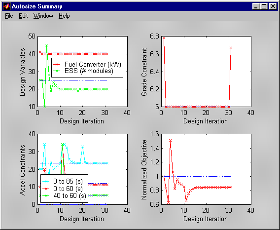
While the autosize routine is running the user will see a figure providing a status update. The information displayed will be dependent on the options selected by the user. The the design variables, the constraints, and the normalized objective will always be displayed. The normalized objective is equal to the normalized sum of all of the objective values.

Figure 3: Autosize Results Figure
When the routine has finished, summary information will be displayed in the Matlab command window, a summary figure (see Figure 3) will be displayed and all values will be updated both in the workspace and the GUI.
Last Revision: 2/9/01:tm