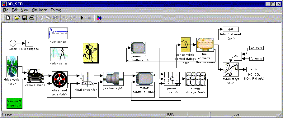
Figure 1. ADVISOR’s series HEV block diagram’s top level
ADVISOR is hybrid of a backward-facing vehicle simulation and a forward-facing simulation.
Backward-facingvehicle simulations answer the question “Assuming the vehicle meets the required trace, how must each component perform?” Simulation programs of this type generally do not include a model of (human) driver behavior, and can predict maximum effort performance only through iteration.
Forward-facingvehicle simulations include a driver model that seeks to modulate throttle and brake commands to follow the trace. The throttle signal is converted into a torque, which is passed down the driveline and ultimately converted to a force which is divided by mass and integrated to compute speed. Simulation programs of this type excel at maximum effort performance calculations, but are often very slow in computing vehicle behavior over a 10+ minute-long trace.
ADVISOR uses a hybrid backward/forward approach that is closely related to the customary strictly backward-facing approach, where each component provides as much torque (or force) as is required by the immediately “downstream” component (i.e. closer to the wheels) to meet the specified trace. ADVISOR’s approach is unique in the way it handles the component performance limits in its backward-facing stream of calculations and in the addition of a simple forward-facing stream of calculations. The two overriding assumptions that describe ADVISOR’s combination of the backward-facing and forward-facing approaches are:
The role of these assumptions is highlighted in the discussion of ADVISOR’s simulation approach below.

Figure 1. ADVISOR’s series HEV block diagram’s top level
Figure 1 shows the top level of ADVISOR’s series HEV model, programmed in the MATLAB®/Simulink® environment. Arrows indicate data flow; boxes represent data processing elements or groups thereof. For example, the box labeled “gearbox” contains all data processing elements, such as “Sum” and “Product” blocks and look-up tables, necessary to model the vehicle’s single- or multi-speed gearbox. Arrows feeding data from left to right, such as the arrow going from the “motor/controller” block to the “power bus” block, are generally part of the backward-facing part of the model, passing torque, speed, and power requirements up the drivetrain. The arrows that loop back to pass data from right to left, such as the arrow from the “motor/controller” to the “gearbox” block, are part of the forward-facing part of the model, transmitting available torque, force, speed, and electrical power through the drivetrain. Each block references MATLAB® data, such as a loss or efficiency table, that describes the performance of the appropriate component.
To illustrate the way ADVISOR’s backward- and forward-facing parts relate to each other, we consider the simulation of a hypothetical series HEV’s maximum-effort acceleration. This will make an interesting and appropriate example because ADVISOR is unique in the way it handles drivetrain performance limits, and the drivetrain will always be operating at its limit during the acceleration. ADVISOR describes a maximum-effort acceleration by requiring a 322-km/h step, assuming that this is a greater speed than the vehicle will ever reach. Below, we step through ADVISOR’s calculation paths—first the ‘required’ values of the variables (backward-facing results) and then the ‘available’ values (forward-facing results).
The leftmost block in Figure 1’s chain of drivetrain components is labeled “drive cycle.” This is where the required speed versus time trace data is input to the simulation. The vehicle and component data defined by text files in the database are referenced in the appropriate component model. For example, all motor performance data are referenced in the “motor/controller” block.
The “drive cycle” block transmits the required speed trace to the “vehicle” block. The “vehicle” block includes no drivetrain performance limits, and straightforwardly uses the required trace to compute the average tractive force and average speed required over the time step. These requirements are passed from the “vehicle” block to the “wheel/axle” block via the lead that connects the two in Figure 1.
The “wheel/axle” block includes the transformation of force and linear speed to torque and rotational speed and the effects of tire slip, wheel and axle bearing drag, and wheel and axle rotational inertia. Only the tire slip model includes performance limits and therefore merits further discussion.
The tire slip model relates weight on the tire, longitudinal force, vehicle speed, and slip in an equation or set of tables, where
 . (EQ. 1)
(A list of parameters is included at the end of this document.) The tire slip is limited to some maximum value, and this in turn limits the transmissible tractive force. Using vehicle loss parameter information borrowed from the “vehicle” block, the required speed is limited according to the acceleration possible with the traction-limited force. ADVISOR solves the following equations simultaneously at the maximum slip condition to determine the maximum force and acceleration:
 (EQ. 2)
 . (EQ. 3)
See the block ‘<vc>/traction control’ in any of ADVISOR’s vehicle block diagrams for details.
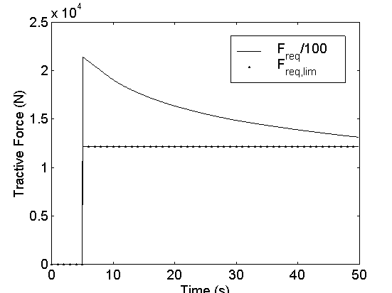
Figure 2. Required tractive force: Freq, required to meet trace; Freq,lim, subject to tire traction limits
As shown in Figure 2, the tractive force required to meet the trace in the example peaks at roughly 2.1x10⁶ N, coincident with the step in the trace speed, and then falls off as the vehicle accelerates to approach the trace. (Figure 3 shows the calculated vehicle speed.) The maximum tractive force the tires can transmit is constant at roughly 1.2x10⁴ N.
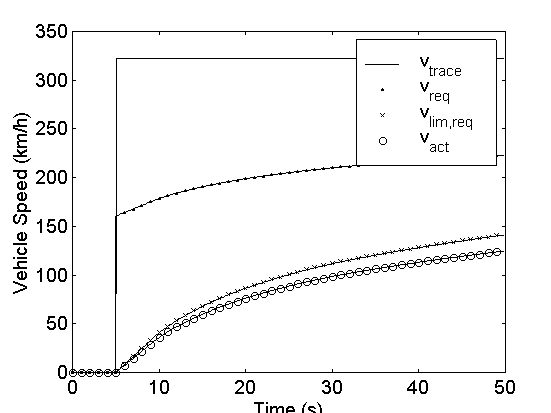
Figure 3. Required and actual vehicle speed
Figure 3 shows the various required vehicle speeds in the model. The required trace that is output by the “drive cycle” block is shown as vtrace. The average speed required over the time step that is output by the “vehicle” block is shown as vreq. The influence of the tire slip model can be seen by comparing vreq with vlim,req, which is the vehicle speed possible given the tire’s traction limit. Finally, vact is the vehicle’s actual speed, shown here for reference. Note that the actual vehicle speed is lower than the tire limit because in this example it is limited by the components “upstream” of it.
With tire slip limits enforced, the required wheel speed is calculated as follows:
 (EQ. 4)
Required torque input to the axle is computed by summing the torque required to provide the necessary average tractive force, the torque required to overcome bearing losses and brake drag, and the torque required to accelerate the wheels’ and axles’ rotational inertia.
 (EQ. 5)
The “wheel/axle” block sends its torque and speed requirements to the “final drive” block, which includes no limits and straightforwardly transforms the torque and speed requirements with its gear ratio and torque loss. The next in line in Figure 1, the “gearbox” block, likewise includes no performance limits. After transforming the torque and speed required of it, the “gearbox” passes the requirements upstream to the “motor/controller” block.
The next section will focus on the motor and motor controller model because it enforces a number of performance limits, and is perhaps the component model most representative of ADVISOR’s hybrid backward/forward approach. Although the motor is not the end of the line of backward-facing calculations in ADVISOR, it will be the most ‘upstream’ component discussed here. Discussion of the components further upstream such as the energy storage system would not significantly further illuminate ADVISOR’s unique approach.
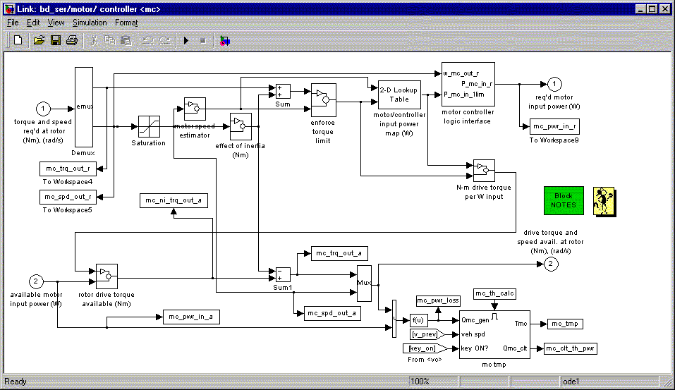
Figure 4. ADVISOR’s motor/controller block diagram
The top half of ADVISOR’s motor/controller model, shown in Figure 4, is dedicated to the backward-facing part of the simulation. The required output torque and speed are input at the top left-hand corner of the block diagram, and the required input power is output at the top right-hand corner.
Three different performance limits are enforced in the backward-facing part of the “motor/controller” block. The required speed is limited to the motor’s maximum speed. The required torque is limited to the difference between the motor’s maximum torque at the limited speed and the torque required to overcome the rotor inertia. The limited torque and speed are then used to interpolate in the motor/controller’s input power map. Finally, the interpolated input power is limited by the motor controller’s maximum current limit. This behavior is described in the following equations:
 (EQ. 6)
where , (EQ. 7)
f is the functional relationship described by the motor map, , (EQ. 8)
and (EQ. 9)
where f1is the functional relationship described by the motor’s torque envelope. For cases where the vehicle missed the required trace by more than 1 mph (1.6 km/h) in the previous time step, wmot,lim,req is replaced in Equations 7 and 8 and in the f1function evaluation in Equation 9 by the previous time step’s actual motor speed, given by Equation 10.
 (EQ. 10)
Equation 10 gives an estimate of the previous time step’s motor speed using the only speed that is truly calculated in ADVISOR–the actual achieved vehicle speed, given by the MATLAB variable ‘mpha’ and represented in the equation above as vact. vavail is the vehicle speed associated with the available driveline speeds given by MATLAB variables such as mc_spd_out_a, which is equivalent to wmot,lim,reqin Equation 10 above. (See Equation 12 below for more information on vavail.) Therefore, the ratio (wmot,lim,req/vavail) includes the effects of gear ratio, tire rolling radius, and tire slip that relate motor speed to vehicle speed.
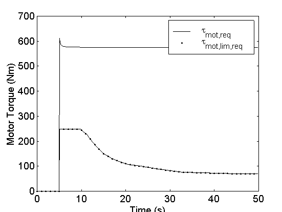
Figure 5. Required motor torque: tmot,req, required into gear reduction; tmot,lim,req, subject to motor torque limit
Figure 5 illustrates the effect of Equation 9. In the maximum-effort acceleration example, the motor is asked to produce more than its maximum torque. At times after 5 s, the maximum torque capability represented by tmot,lim,reqis used to formulate the motor/controller input power requirement.
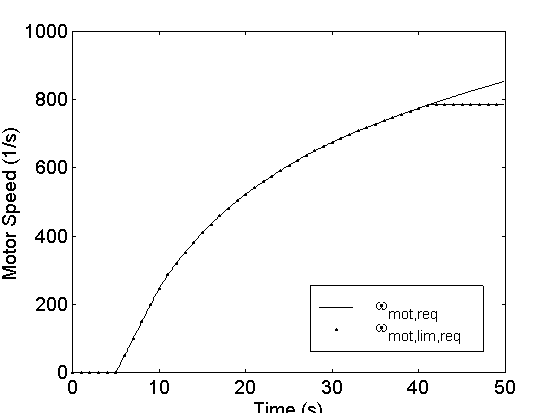
Figure 6. Required motor speed: wmot,req, required into gear reduction; wmot,lim,req, subject to motor speed limit
Figure 6 illustrates the effect of Equation 8. After about 42 s, the motor is required to exceed its maximum speed to provide the wheel and axle (via a gear reduction) the maximum speed they are capable of handling. wmot,lim,req, coincident with wmot,reqcurve for most of the acceleration, is used to formulate the motor input power requirement.
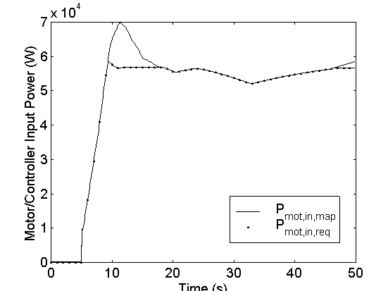
Figure 7. Required motor/controller input power: Pmot,in,map, computed by map; Pmot,in,req, subject to controller current limit
Figure 7 illustrates the effect of Equation 6. Pmot,in,map is the input power required to power the motor at its maximum-limited torque and speed. Pmot,in,reqis the power that the motor/controller requires of the power bus, which must in turn be provided by the batteries and/or the generator. For the example case of a maximum effort acceleration, Figure 7 indicates that between about 9 s and 18 s the motor requires more power than it is capable of handling, according to its current limit, to meet the limited torque and speed requirements.
The bottom part of Figure 4, not enclosed in a dashed box, is the forward-facing part of the motor/controller model. It accepts as input the available input power, on the bottom left of the figure, and produces as outputs the available rotor torque and speed.
To compute the torque that can be produced by the motor/controller given the available input power, the motor/controller efficiency computed during the backward-facing calculations is used, modeled as tmot,lim,req/Pmot,in,mapin Equation 11 below.
 . (EQ. 11)
Note that the model accounts for the torque required to accelerate the motor’s rotor using the motor shaft’s required acceleration. For maximum-effort acceleration runs, the required acceleration is limited by the tire slip, and this acceleration is usually greater than what is possible given the drivetrain limits. Therefore, the motor’s inertial effect is overestimated for maximum-effort acceleration runs. We see below that this overestimation has negligible effect on ADVISOR’s fidelity.
The motor speed that the “motor/controller” block outputs, which is termed “available” speed, is the motor’s actual speed only if there are no torque or power limits active during the current time step. Figure 6 indicates that the motor model’s output available speed is equal to wmot.lim,req as computed in Equation 8. This means that the “available” motor speed is the required motor speed subject to the motor’s speed limit. If the available motor torque is less than the required motor torque, however, there is insufficient torque for the motor to accelerate to its required speed. This would cause the “available” motor speed output by the “motor/controller” block to be greater than the actual speed of the motor.
The available motor torque is transformed by the efficiencies of the gearbox and the final drive (which are computed during the backward-facing calculations), and their gear reductions. This results in available drivetrain torque and speed input to the wheel and axle. Wheel slip plays a role in transforming the available speed only if it is different from the required speed, as is the case if a drivetrain component’s speed limit is encountered. This is described in the equation below:
 ,(EQ. 12)
where slip is recomputed here using the available tractive force and vavail is the component speed capability-limited vehicle speed.
Slip plays no role in computing tractive force beyond limiting the request in the backward-facing calculations. Because no calculation in the upstream components acts to increase the tractive force, the limit enforced by the slip model remains in place through the forward-facing calculations in the “wheel/axle” block.
After accounting for losses in the axle and dividing by the tire’s rolling radius, ADVISOR arrives at an available tractive force. Solving Equation 3 for the speed at the end of the time step, ADVISOR arrives at an estimate of the actual vehicle speed. ADVISOR compares this force-based estimate of vehicle speed with that derived from Equation 12, and chooses the minimum of the two for the actual vehicle speed, vact, plotted in Figure 3. In this way, the computed vehicle speed never exceeds that possible given the torque and force available from the drivetrain or the speed that corresponds to any drivetrain component speed limits that might be active.
| Freq | tractive force required to meet trace, ADVISOR variable=’veh_force_r’ |
| Icon,max | maximum motor controller current, ADVISOR variable=’mc_max_crrnt’ |
| Jmot | motor rotational inertia, ADVISOR variable=’mc_inertia’ |
| Jwh | wheel/axle assembly rotational inertia, ADVISOR variable=’wh_inertia’ |
| Pmot,avail | (electrical) input power available to the motor/controller, ADVISOR variable=’mc_pwr_in_a’ |
| Pmot,in,req | (electrical) input power required by the motor/controller, ADVISOR variable=’mc_pwr_in_r’ |
| rwh | tire rolling radius, ADVISOR variable=’wh_radius’ |
| slip | tire slip fraction, ADVISOR variable=’wh_slip_r’ for required slip |
| Vbus | bus voltage (equal to battery pack voltage), ADVISOR variable=’pb_voltage’ |
| vact | actual vehicle speed at end of time step, ADVISOR variable=’mpha’ |
| vreq | required vehicle speed (average over the time step), ADVISOR variable=’veh_spd_r’ |
| vtrace | required vehicle speed (at end of time step), ADVISOR variable=’cyc_mph_r’ |
| tmot,avail | available motor torque, ADVISOR variable=’mc_trq_out_a’ |
| tmot,lim,req | required motor torque, subject to motor torque limit |
| tmot,req | required motor torque, ADVISOR variable=’mc_trq_out_r’ |
| twh,req | torque required to wheel/axle from driveline, ADVISOR variable=’wh_trq_r’ |
| wmot,act,prev | motor’s rotor speed during previous time step, ADVISOR variable=’mc_spd_est’ |
| wmot,max | maximum motor speed |
| wmot,req | required motor speed, ADVISOR variable=’mc_spd_out_r’ |
| wmot,lim,req | motor speed required, subject to motor speed limit, ADVISOR variable=’mc_spd_out_a’ |
| wwh,avail | available wheel speed, ADVISOR variable=’wh_spd_a’ |
| wwh,req | required wheel speed, ADVISOR variable=’wh_spd_r’ |
Beginning of Chapter 3
Back to Chapter 2
Forward to Appendices
ADVISOR Documentation Contents
Last Revised: 7/20/00:AB