Role of subsystem in vehicle
The control strategy determines at what torque and speed the engine should operate, to generate electric power via the generator, given the conditions of the motor, ESS pack, and/or the engine/fuel converter itself. Usually such a strategy is designed to minimize fuel use or emissions or maximize ESS pack life.
Description of modeling approach
The built-in series controls strategy offers flexibility in the fuel converter (FC) operation:
When the FC is on, its power output tends to follow the power required by the bus, accounting for losses in the generator so that the generator power output matches the bus power requirement. However,
Variables used in subsystem
There are eleven variables that determine the control strategy. Their influence on the engine operation are shown in the schematics below, and they are described in the following table.
Determining FC State (on/off)

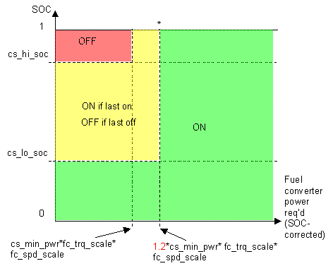
The above figure indicates the commanded fuel converter (FC) state as a function of ESS pack SOC, SOC-corrected fuel converter power required, and the FC’s previous state.
SOC-corrected fuel converter power required is computed by:
The asterisked boundary, which refers to the minimum power requirement to cause the FC to turn on when it was previously off, has more dimensions than could be included in this graphic.
In fact, if the FC was last on and SOC < cs_hi_soc, the engine will stay on regardless of power command. It may be useful to imagine that the yellow portion of the figure continues right of its current position, filling the space SOC > cs_lo_soc and (power command) > (1.2*cs_min_pwr*fc_trq_scale*fc_spd_scale).
However, if the FC was previously off, and (the average of the last 5 s of fuel converter power command) > (1.2*cs_min_pwr*fc_trq_scale*fc_spd_scale), AND (the time since the FC was last on) > cs_min_off_time, the FC will start. This temporal component of the logic isn’t displayed in the figure above.
Finally, regardless of all other conditions, if the power required by the bus is greater than the ESS pack capability, the FC will turn/stay on.
Determining FC Output Power
FC output power is as required by the generator to fulfill the bus requirement, with the following exceptions:
Determining FC Torque and Speed
The current version of the control strategy is designed for heat engines characterized by torque and speed.1 In a control script executed before the simulation is run, the locus of highest efficiency torque/speed points is computed over the range of genset (the combination of the engine and mated generator) powers. The control strategy keeps the FC torque and speed on this locus using a lookup table defined by cs_pwr and cs_spd.
| Variable | Units | Description |
| cs_hi_soc | – | highest desired battery state of charge |
| cs_lo_soc | – | lowest desired battery state of charge |
| cs_charge_pwr | W | cs_charge_pwr*fc_spd_scale*fc_trq_scale*((cs_soc_hi+ cs_soc_lo)/2-SOC) is the SOC-stabilizing adjustment made to the bus power requirement |
| cs_fc_init_state | – | 1=>fuel converter (FC) is initially on; 0=>FC initially off |
| cs_max_pwr | W | cs_max_pwr*fc_spd_scale*fc_trq_scale is the maximum power commanded of the fuel converter unless SOC<cs_lo_soc |
| cs_min_pwr | W | cs_min_pwr*fc_spd_scale*fc_trq_scale is the minimum power commanded of the fuel converter |
| cs_max_pwr_fall_rate | W/s | cs_max_pwr_fall_rate*fc_spd_scale*fc_trq_scale is the fastest the fuel converter power command can decrease (this number < 0) |
| cs_max_pwr_rise_rate | W/s | cs_max_pw_rise_rate*fc_spd_scale*fc_trq_scale is the fastest the fuel converter power command can increase |
| cs_min_off_time | s | the shortest allowed duration of a FC-off period; after this time has passed, the FC may restart if high enough powers are required by the bus |
| cs_pwr | W | cs_pwr*fc_spd_scale*fc_trq_scale is the vector of FC powers that define the locus of best efficiency points throughout the genset map |
| cs_spd | rad/s | cs_spd*fc_spd_scale is the vector of FC speeds in locus of best efficiency points, indexed by cs_pwr*fc_spd_scale*fc_trq_scale |
Example:
Pure Thermostat as a Special Case of the General Control Strategy
To implement a pure thermostat control strategy, use something like the following values of the control strategy parameters:
cs_hi_soc=0.8; % FC shuts off at 80% SOC
cs_lo_soc=0.4; % FC turns on at 40% SOC
cs_fc_init_state=0; % FC initially off
cs_min_pwr=max(fc_max_trq.*fc_map_spd)*.5; % FC operates at no less than 50% max power when on
cs_max_pwr=max(fc_max_trq.*fc_map_spd)*.5; % FC operates at no more than 50% max power when on
cs_charge_pwr=0; % FC output power, when on, is independent of SOC
cs_min_off_time=inf; % FC never restarts before SOC falls below cs_lo_soc
cs_max_pwr_rise_rate=0; % FC output power doesn’t increase while on
cs_max_pwr_fall_rate=0; % FC output power doesn’t decrease while on
1It is possible to use it, however, to control other types of fuel converters such as fuel cells. The fuel cell vehicle model included with ADVISOR 2.0 gives an example of this workaround.
* * * * *