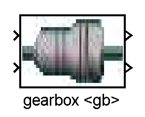
Figure 1. Top Level of New Library Blocks
The Simulink block diagrams have been re-worked and re-organized to provide a more easy to use interface. This help file overviews the changes that have occured and their implications. In addition, a tutorial on how to convert existing library blocks to the new structure is presented.
Contents ——–
The new layout encapsulates all model information behind a Simulink Masked Subsystem. All communication in and out of the block is then routed through direct connections between other blocks (nothing new here: these are the torque and speed requests passed from one block to another) and through muxed sensor and control signal lines (this is new). These lines allow the user to pick-off specific signals using bus select properties.
Therefore, all communication with a model is forced through one of the following places:
- Dedicated INPUT/OUTPUT ports which tie blocks together (e.g., the torque and speed request line from the transmission to the IC engine) - Sensor signal bus-bar which holds all of the signals available FROM a model - Control signal bus-bar which holds all of the signals that will GOTO a model - Intialization script files which can be loaded on the workspace (default ADVISOR behavior) or directly into each model.
Some of the advantages of this new re-organized set-up of the ADVISOR Simulink Library versus the original ADVISOR library layout are as follows:
- The external data needs of each model are explicitly laid out. This makes it much easier to hook up one model block with another, develop new powertrain configurations, and test models.
- Each model is encapsulated in its own “function space”. This allows you to use more than one of the same component in a single block diagram. Furthermore, each component can be loaded with separate data. - The new layout makes it much easier to test and validate models in a stand-alone fashion.
Visually, there is no discernable difference at the top-most level. The first sub-layer defines the hard-coded input output lines, the sensor signal bus line, and the control signal bus line. The second sub-layer defines the sensor signals and the control signals from individual scoped GOTO/FROM blocks. The third sub-layer contains the actual model.

Figure 1. Top Level of New Library Blocks
As can be seen, the top level of the new library blocks do not look different from the previous ADVISOR library blocks.
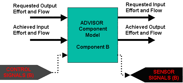
Figure 2. First Sub-Level of New ADVISOR Library Blocks
At this level, the muxed signal bus and muxed sensor bus can be seen. Note that these are global tags which allow the component model to transfer data to and from other blocks such as system controllers.
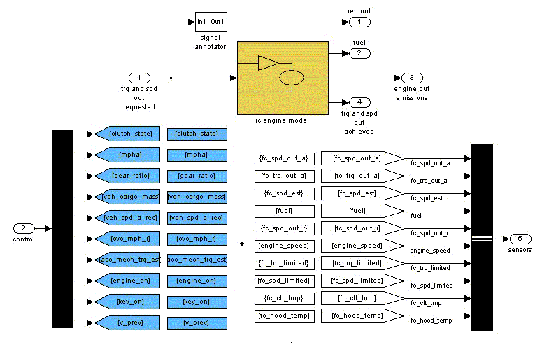
Figure 3. Sub-Level Two
At this level the control and sensor signals are muxed/demuxed respectively. It is at this level that the original model can be found. Scoping blocks are used to scope the visibility of GOTO and FROM tags. Dedicated INPUT/OUTPUT signals are passed into the model from the top-most level.
For the most part, converting from an old-format model to the new re-organized system stated above is straight forward. GOTO and FROM tags must be set up as scoped but, for the most part, models can be left as-is. However, if ToWorkspace blocks are used in the original model, a new toWorkspace block called enhancedToWorkspace must be substituted. The enhancedToWorkspace block dynamically renames the toWorkspace data to prevent name-space clashes when more than one of the same block model is used.
### The toWorkspace and other Name-space collision Problems
One of the design goals for the reorganized library is the ability to use more than one component model in the same block diagram (for example, two motors in a through-the-road hybrid configuration). Alternately, one may wish to use more than one component from a component family in the same block diagram (e.g., an IC Engine for main traction power and a Fuel Cell for auxiliary loads–both components are fuel converters). The limiting factors here are three-fold: name-space collisions on input variables, name-space collisions on sensor and control signal bus tags, and name-space collisions on toWorkspace variables.
The name space collision on input variables can be circumvented by placing each component variable in a MASK (essentially, a “function workspace”). That is, initialization m-files can be loaded directly into the components they are relevant to. This would allow us to define two motor components in the same block diagram and initialize each one with a different data set. Thus, the new library reorganization alleviates the first concern on input varible name-space collision.
The second concern deals with the control and sensor bus signals. If we use more than one component block in a block diagram, we will need to be able to differentiate between the sensor and control signals of each component block. This has been done by giving each component a “name”. A MASK initialization file in the component then renames each block’s SENSOR and CONTROL tag as “nameSensors” and “nameControl” respectively. Thus, one can now differentiate between two instances of a component in a block diagram. One downside is that in MATLAB version 6.1, the renaming of the sensor and control tags requries one to disable the library link. This prevents library updates from automatically propogating to the component models. However, MATLAB version 6.5 appears to support dynamic GOTO/FROM tag renaming fine (there is a check box in the mask that says “allow library block to modify its contents”–this must be checked).
The third concern is regarding the toWorkspace variables and is more difficult. The Simulink “toWorkspace” block is designed to take variables from the Simulink “universe” and place them into the MATLAB workspace as arrays. The original ADVISOR library uses a combination of two different ideas to log variables to the workspace. The first is to place toWorkspace blocks within the component models themselves at the areas where the information is generated. The second is to use an SDO (standard diagnostic output) block to log variables. That is, GOTO tags are used to transmit all signals to a common block area where all the toWorkspaces are used at once.
There is no right or wrong between these two ways of logging variables. However, Simunlink has some limitations regarding the toWorkspace block and which type of data logging one chooses has implications for the final library implementation. Let me explain further.
Simulink toWorkspace blocks do not allow the same variable name to be logged to more than once. Therefore, even if we encapsulate each component model behind a MASK, if two component models define the same variables for toWorkspace blocks, the Simunlink model will not run due to variable name-space collisions during toWorkspace logging. One option is to remove all toWorkspace blocks from a model. The variables can then be logged by sending sensor signals to an SDO block. This idea has many merits which we will return to later.
Another option which has been pursued here is the use of dynamic toworkspace block re-naming. In this option, the name given to each component block is used to create the toWorkspace variable to log. For example, if one motor/controller component is used named mc1 and another is used callled mc2, then the variable *_trq_out_a will be logged to the workspace as mc1_trq_out_a and mc2_trq_out_a. The major drawback for the dynamic toWorkspace block is that it does not support library linking in either MATLAB 6.1 or 6.5. If the SDO approach is taken, there will be no linking issues. The major drawback of the SDO block is that significant manual effort is required to set it up.
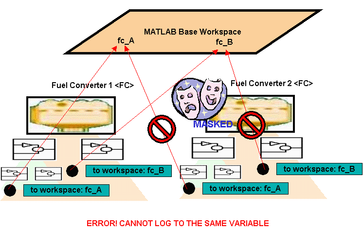
Figure 4. Simulink Does not Allow Logging to the Same Variable Name
As can be seen in the figure above, even if two masked compoents exist in a model, an error will occur upon attempt to log to the same variable name more than once.
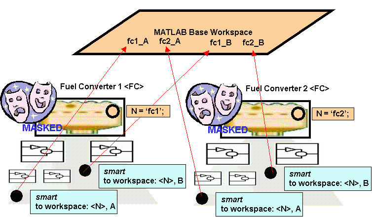
Figure 5. The enhancedToWorkspace block allows for dynamic renaming of the variable to log to
The enhancedToWorkspace block allows one to get around the namespace collision issues by using the unique component name to append to the front of a variable name creating a unique variable to log to.
Using the New Library Blocks ————————————————
There are two ways to use the new libary block system in ADVISOR. The first way is basically transparent. Because of the nature of masked sub-systems in Simulink, if input information is not defined within the components MASK workspace (a “function workspace”), the code will open itself up to look on the MATLAB workspace. The MATLAB workspace is where ADVISOR traditionally loads initialization/input files and retrieves output variables. Therefore, nothing has changed.
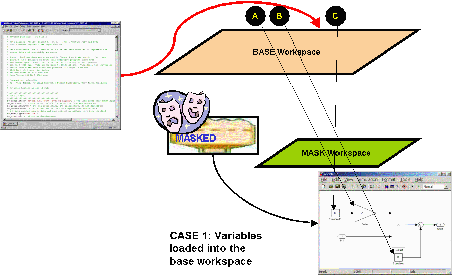
Figure 6. Initializing Component Models from the Base Workspace
Simulink components will look in the base workspace if a required variable is not defined in their MASK Workspace
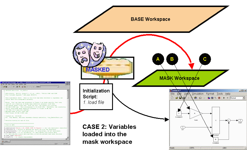
Figure 7. Loading from the MASK Workspace
Components can also initialize from the mask workspace.
The alternate way to use the new library blocks is from a Simulink mode. In this mode, one opens the Simulink block diagram and sets up the intialization files into the dialogue boxes of the component blocks themselves. The model is then run entirely in Simulink (though output can be browsed by calling the gui_post_process.m and ResutlsFig.m file to browse the workspace). This alternative is generally left to more advanced users.
The component dialogue box consists of the following:
- General Name of the component (used for logging variables dynamically as well as re-naming control and sensor signal GOTO/FROM tags) - Log Variables On/Off Switch (used to turn on/off the dynamic toWorkspace feature)
- Initialization File Name (the name of the m-file to load to initialize the component–leave blank to look for variables in the base workspace) - Modification Cell (a cell array consisting of any number of rows and two columns–the first column contains variable names to override/modify and the second column contains the new values to assign) - Icon Image (to change the icon, type the picture file into this entry box) - DEBUG on/off flag – changes how verbose printing to the workspace is
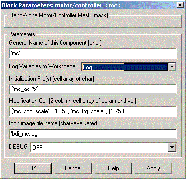
Figure 8. Component Initialization Mask
The component initialization mask is used to setup individual components for more advanced runs (i.e., runs done directly from Simulink versus using the ADVISOR GUI)
The new component libraries have been placed in with the other library model files in models/library. They have a number trailing after them to distinguish them from the original model files. For example, lib_electric_machine2.mdl contains re-organized motor/controller library components. In addition, if one types simulink from the MATLAB command and looks at the Simulink Library Browser, you will note that the reorganized ADVISOR library models are all available from the Library Browser (click on the “+” sign to load the libraries").
Return to ADVISOR Documentation
last modified: 8/5/2003: mpo