 |
 |
| Mechanical Accessory Loads (powered by mechanical shaft) |
Electrical Accessory Loads (powered by electrical source) |
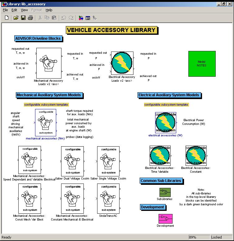
Advanced users of ADVISOR will notice two new blocks in the ADVISOR vehicle powertrain block diagrams: Mechanical and Electrical Accessory Loads. These blocks represent dedicated auxiliary load systems. The difference between the two blocks is the source of energy. The mechanical accessory blocks obtain their energy from a spinning shaft. Electrical loads require an electrical source (e.g., power bus) to power their loads.
|
|
| Mechanical Accessory Loads (powered by mechanical shaft) |
Electrical Accessory Loads (powered by electrical source) |
Each block contains a forward model and a backward model. In the backward model, the auxiliary blocks modify torque or power requests going up-stream to include that extra torque or power required to satisfy the accessory loads. In the forward model, torque or power is subtracted from power generated up-stream and sent to auxiliary loads. The remaining power flows downstream to the powertrain.
These powertrain blocks are contained in a dedicated accessory loads library: lib_accessory (see <ADVISOR main directory>\models\library). The lib_accessory library makes extensive use of configurable sub-systems. Configurable sub-systems allow new models to be switched into a simulink model “on the fly”. One such model allows the simulation of speed-dependant mechanical accessory loads.
To the casual user, these changes are transparent. The configurable subsystems are switched using an m-file function called adjust_config_bds.m (located in <ADVISOR main directory>\gui). The adjust_config_bds.m file is called by the GUI after the user sets up the vehicle definition. The adjust_config_bds.m file switches in the appropriate configurable subsystem model based upon version and type, and\or variables sent to the workspace.
It is now possible to add your own user models as configurable subsystems in the library. The process is relatively straightforward for users versed in Simulink. As an example, let us make a new auxiliary load file in the accessory library (in lib_accessory.mdl). Start by unlocking the library (edit>unlock library). Next, copy and past an existing configurable sub-system block. Break the links between the new block you are working on and the old block (right click and link options>disable link then link options> break link). Enter the block and keep the inputs and outputs the same but change the “guts” of the model to implement your new system. Now, click on the configurable subsystem template in the library. Place a check box next to the new model you have just made. Viola! You now have a configurable subsystem model.
Next, edit adjust_config_bds.m to add the new configurable subsystem choice to the appropriate portion of the switch-case menu. You may need to create your own custom m-file that will load in the appropriate initialization information for your new model. You can create a flag variable to use for adjust_config_bds if you do not wish to create a new version/type.
Last revised: [30-April-2002] mpo
Created: [17-March-2002] mpo